I need a bit of help as I think something has gone missing from this piece of boot release linkage.
I *think* there should be some sort of insert which fits into the hook on the end of the cable in the pic below, and carries the end of a pushrod. Can anyone confirm this?
I appreciate that it is not always easy to interpret a picture like this out of context, so here's some background and some pics of the rest of the complicated linkage. So in a few pics' time I'll show you the other end of the cable, and what it does.
Story so far: As part of my body restoration and respray last year, I changed tailgates, and that change, combined with the residue of the soda blasting, caused a string of irritating little problems which are now almost fixed. The hatch pins are sorted now, and I have got the the jaws that hold the pins all unstuck and free moving where the soda blasting residue had stuck them up. I have also reconditioned the motor, which is now working extremely well having also been choked up with soda residue.
So now the pins work and the jaws work and the motor goes round and round like anything.
The final problem is that the linkage between the motor and the pins has now fallen to bits, probably because I had to poke and prod it all from within the car to get the boot open while the motor was bust.
Here are some pics, to explain how it all works, as some people may not have had to take all this to bits, and other people with early or LHD cars may have manual releases.
Imagine you are sitting in the boot looking back at the latch mechanism. Here is the big picture view of the latch, once the trim panel is removed. The main mounting nuts and washers for the mechanism have been removed from the studs left and right.
Take out the latch and in this shot I have highlighted the two rods which open the spring-loaded jaws which grasp the hatch pins.
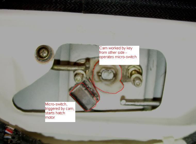
Out of interest for those who have not had this mechanism to bits, in the next pic I have outlined the white nylon rotating cam which is what turns when you operate the key from outside. The cam presses against the micro switch which is the black box to the lower left of the cam, and that starts the motor.
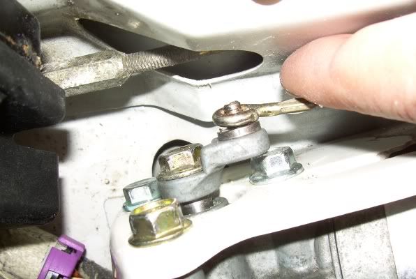
Over towards the driver's side (RHD car), lurks the motor that is triggered. It is bolted underneath the white mounting bracket in this shot, with its gearbox to the left of the pic, and its drive shaft poking up through the mounting bracket, where it drives the rotating cranked arm which carries an eccentric spigot, the thing with the circlip groove in it.
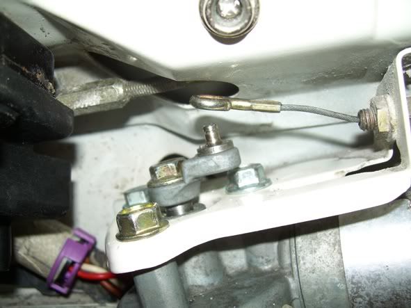
Over that spigot fits a cable end, and yes, this is the other end of the cable that I showed in the top photo. The cable end is supposed to be retained on the spigot by some kind of circlip, which went missing in the body shop so I made one recently out of sheet brass and it's working OK.
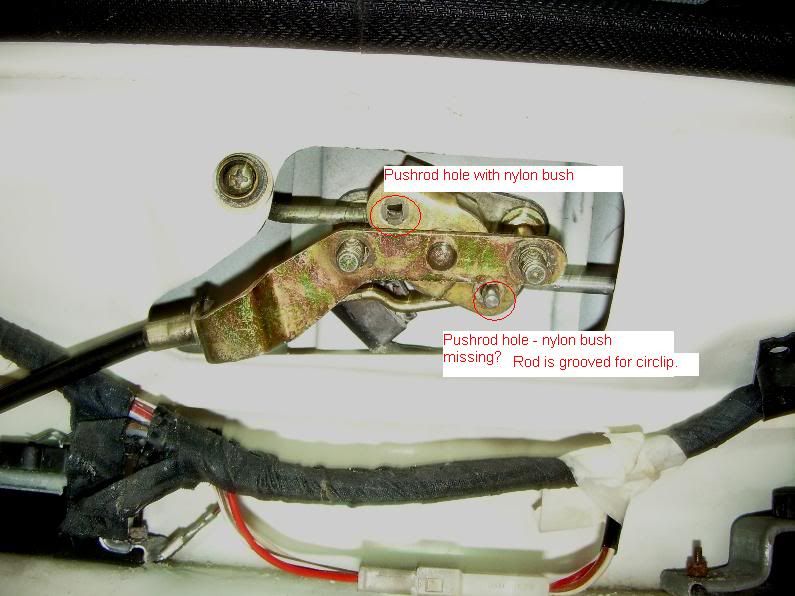
Turning back to the push-pull rods which work the jaws, I showed the inner ends of these earlier, and in the next shot you can see where those rod ends are supposed to pass through the bellcrank. The upper pushrod end is retained by a nylon clip which holds it in alignment (you can just see this, ringed in red). The lower one appears to have a groove for a circlip, and that circlip pinged off recently, making it impossible to open the hatch without applying physical force from inside the boot. Should there also be some sort of nylon fitting on the lower pull-rod end?
The hooked cable end in Pic 1, with the apparently missing bit, is supposed to pull on the bellcrank, somehow, to make the pull-rods pull the jaws.
So, this is what I think I need: am I right?
- a circlip to retain the lower pull-rod end as it passes through the bellcrank, which I can probably made if I have to.
- Some sort of piece which fits within the hook of the hooked wire, and mates it to the bellcrank, and that's the piece which I think is missing altogether.
If there's anyone in North Yorkshire who would be prepared for me to come over and look at their intact linkage that would help, as would a photo of that hooked wire sowing how it connects to the bellcrank.
Thanks in advance...
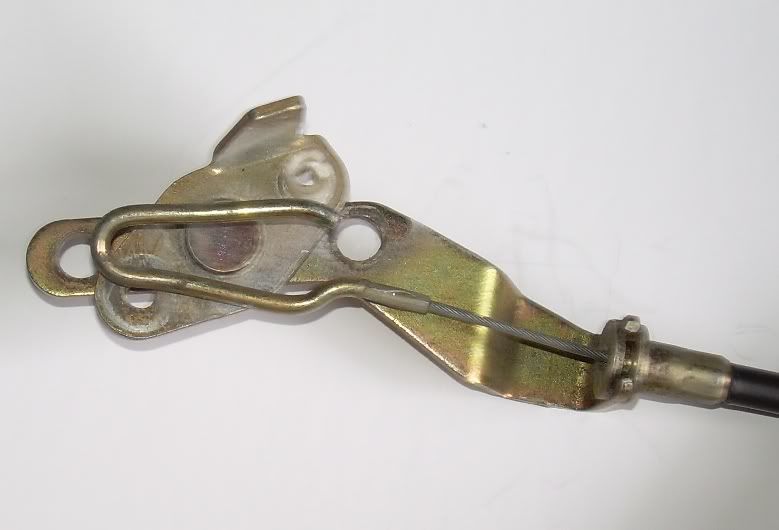
I *think* there should be some sort of insert which fits into the hook on the end of the cable in the pic below, and carries the end of a pushrod. Can anyone confirm this?
I appreciate that it is not always easy to interpret a picture like this out of context, so here's some background and some pics of the rest of the complicated linkage. So in a few pics' time I'll show you the other end of the cable, and what it does.
Story so far: As part of my body restoration and respray last year, I changed tailgates, and that change, combined with the residue of the soda blasting, caused a string of irritating little problems which are now almost fixed. The hatch pins are sorted now, and I have got the the jaws that hold the pins all unstuck and free moving where the soda blasting residue had stuck them up. I have also reconditioned the motor, which is now working extremely well having also been choked up with soda residue.
So now the pins work and the jaws work and the motor goes round and round like anything.
The final problem is that the linkage between the motor and the pins has now fallen to bits, probably because I had to poke and prod it all from within the car to get the boot open while the motor was bust.
Here are some pics, to explain how it all works, as some people may not have had to take all this to bits, and other people with early or LHD cars may have manual releases.
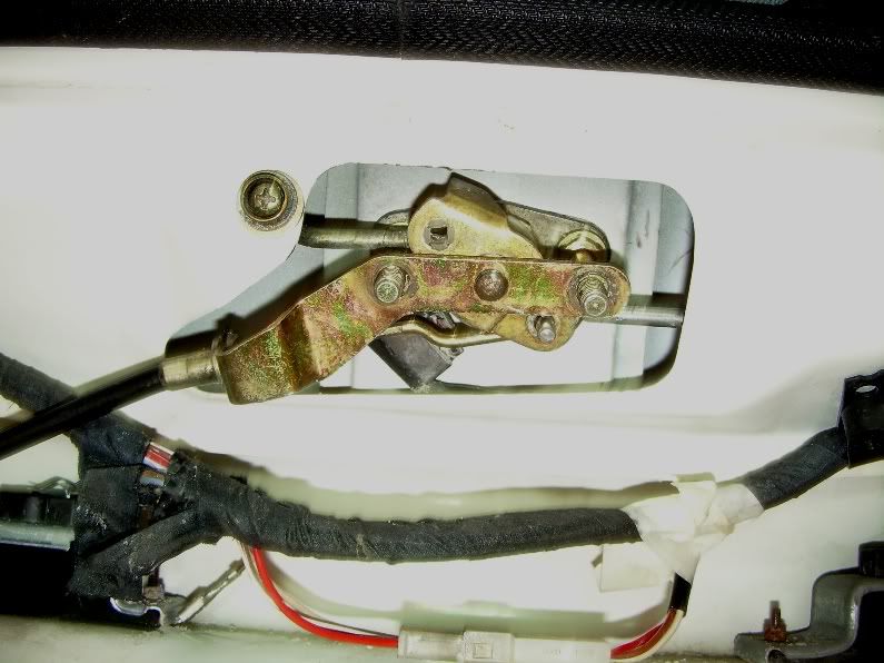
Imagine you are sitting in the boot looking back at the latch mechanism. Here is the big picture view of the latch, once the trim panel is removed. The main mounting nuts and washers for the mechanism have been removed from the studs left and right.
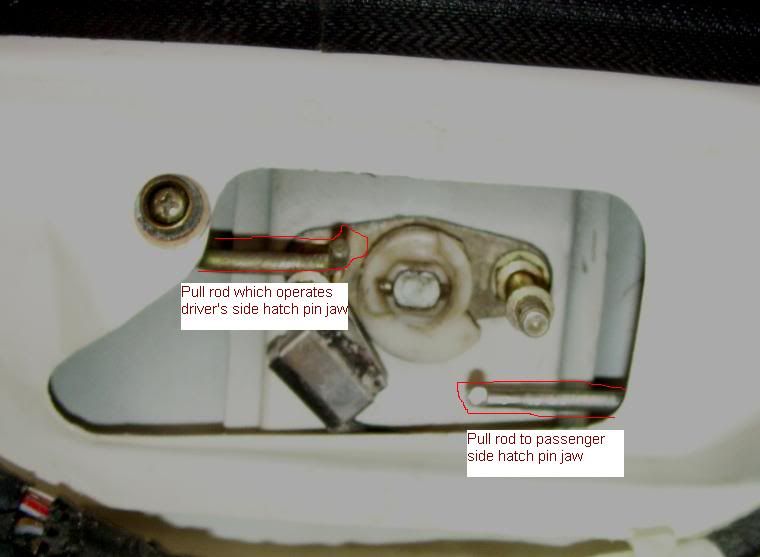
Take out the latch and in this shot I have highlighted the two rods which open the spring-loaded jaws which grasp the hatch pins.
Out of interest for those who have not had this mechanism to bits, in the next pic I have outlined the white nylon rotating cam which is what turns when you operate the key from outside. The cam presses against the micro switch which is the black box to the lower left of the cam, and that starts the motor.
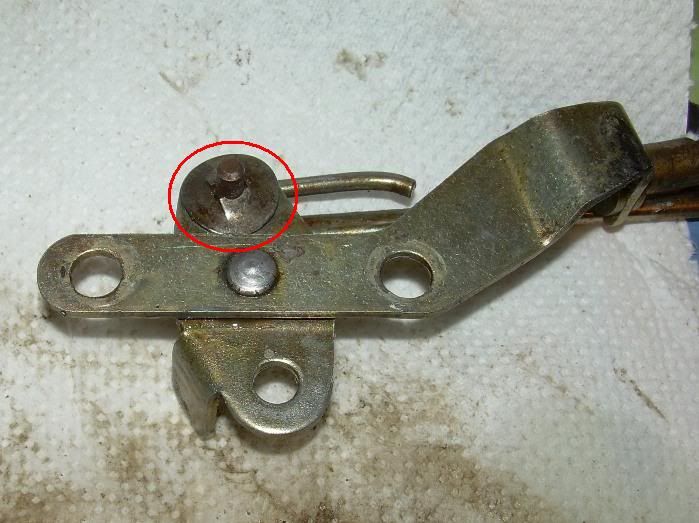
Over towards the driver's side (RHD car), lurks the motor that is triggered. It is bolted underneath the white mounting bracket in this shot, with its gearbox to the left of the pic, and its drive shaft poking up through the mounting bracket, where it drives the rotating cranked arm which carries an eccentric spigot, the thing with the circlip groove in it.
Over that spigot fits a cable end, and yes, this is the other end of the cable that I showed in the top photo. The cable end is supposed to be retained on the spigot by some kind of circlip, which went missing in the body shop so I made one recently out of sheet brass and it's working OK.
Turning back to the push-pull rods which work the jaws, I showed the inner ends of these earlier, and in the next shot you can see where those rod ends are supposed to pass through the bellcrank. The upper pushrod end is retained by a nylon clip which holds it in alignment (you can just see this, ringed in red). The lower one appears to have a groove for a circlip, and that circlip pinged off recently, making it impossible to open the hatch without applying physical force from inside the boot. Should there also be some sort of nylon fitting on the lower pull-rod end?
The hooked cable end in Pic 1, with the apparently missing bit, is supposed to pull on the bellcrank, somehow, to make the pull-rods pull the jaws.
So, this is what I think I need: am I right?
- a circlip to retain the lower pull-rod end as it passes through the bellcrank, which I can probably made if I have to.
- Some sort of piece which fits within the hook of the hooked wire, and mates it to the bellcrank, and that's the piece which I think is missing altogether.
If there's anyone in North Yorkshire who would be prepared for me to come over and look at their intact linkage that would help, as would a photo of that hooked wire sowing how it connects to the bellcrank.
Thanks in advance...
 ]
]